



A system-level guide to DC voltage, rectifier sizing, battery charging, redundancy, protection, monitoring and failure modes.
1. Think in systems, not boxes
An industrial DC system is a complete architecture that combines AC input, rectifiers, DC distribution, battery storage, protection, monitoring and loads. Good design starts from operating scenarios and failure modes, not from choosing a charger model first.
2. DC voltage and adjustment range
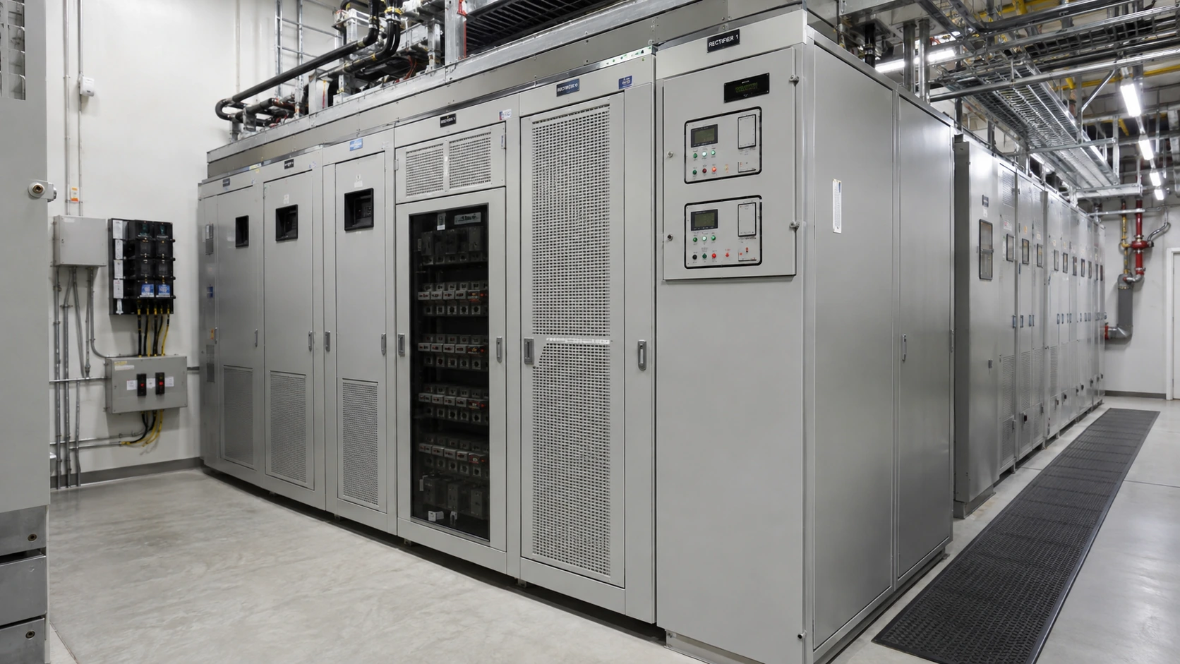
Nominal DC voltage is only one point. The real design must consider float voltage, boost or equalize voltage where applicable, battery end voltage, cable drop and the input range tolerated by every connected load.
3. Rectifier sizing
Rectifier sizing must supply the continuous DC load and the required battery recharge current while respecting redundancy philosophy and ambient derating. Oversizing can be wasteful, while undersizing can prevent recovery after a discharge.
4. Battery charging and chemistry
Charging voltage and current must match battery chemistry and manufacturer limits. Ni-Cd, lead-acid and lithium systems behave differently, so a generic charger setting can reduce life or create unsafe conditions.
5. DC protection is different
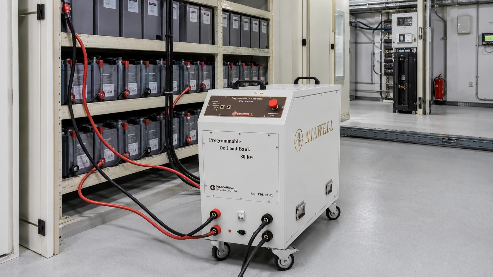
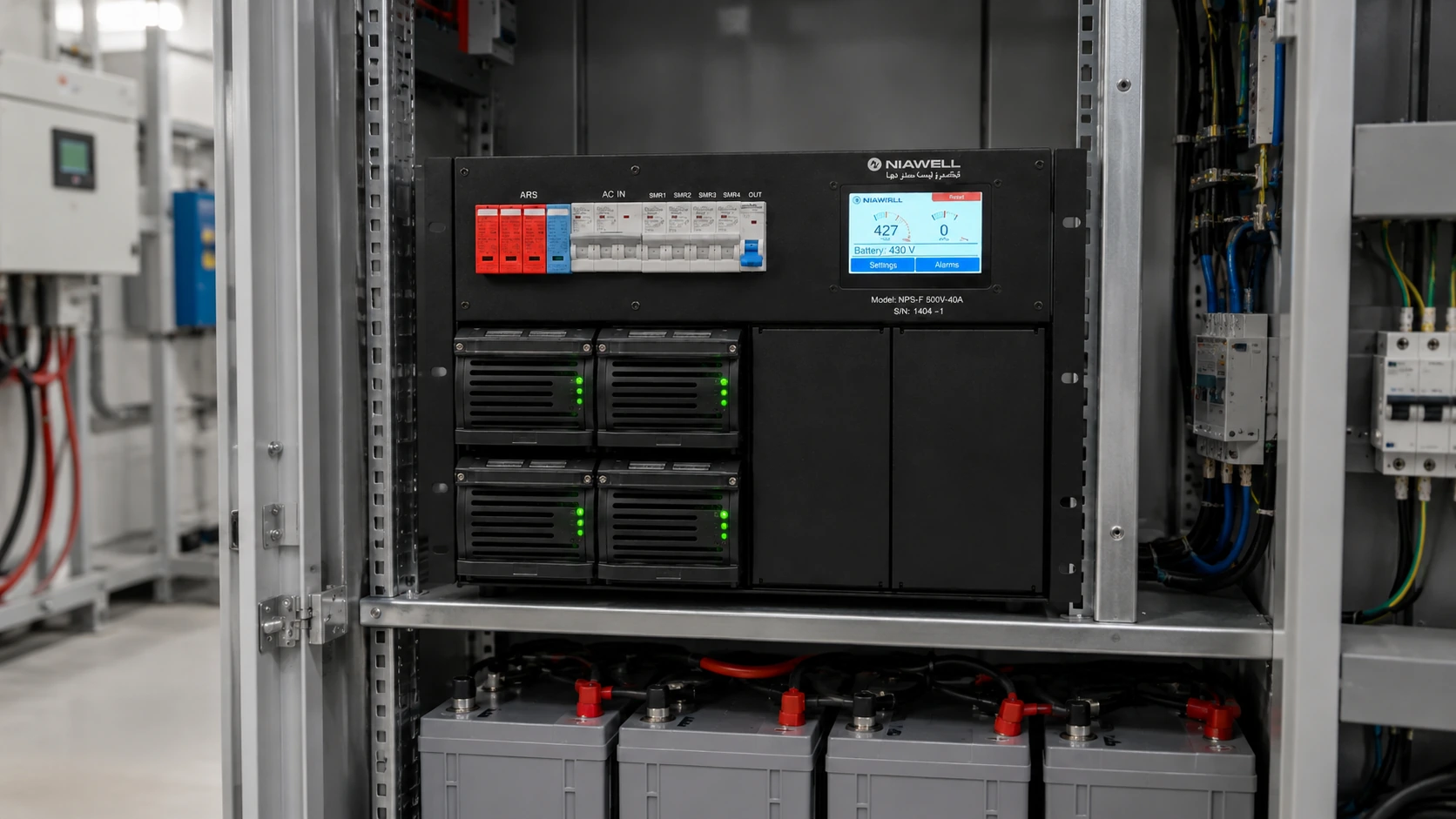
DC fault current does not cross zero naturally like AC. Breakers and fuses therefore need explicit DC ratings, correct polarity where required and enough interrupting capacity for the available fault current.
6. Thermal design and derating
Rectifiers dissipate heat and may derate at high ambient temperature or altitude. Cabinet airflow, fan redundancy, filter maintenance and spacing around modules directly affect available output and service life.
7. Commissioning and failure scenarios
Commissioning should test normal operation, loss of one rectifier module, AC input loss, battery operation, alarm contacts and recovery. Measuring only the output voltage does not prove the system is ready for a real outage.
8. How to write a useful specification
A useful specification states input range, DC output range, continuous load, recharge requirement, redundancy, protection, communication, environmental limits, battery interface and acceptance tests. It avoids vague terms that cannot be verified.
9. Redundancy, selectivity and single-point failures
N+1 modules do not automatically make a system redundant. Shared breakers, control boards, AC feeders, communication or DC bus arrangements may still create single points of failure and should be reviewed explicitly.
10. Monitoring and useful alarms
Useful alarms tell the operator what action is needed: module failure, battery low voltage, DC high or low voltage, ground fault, AC loss and communication failure. Too many unprioritized alarms reduce operator response quality.
11. A simple preliminary sizing example
For preliminary sizing, add the continuous DC load to the desired recharge current, then apply redundancy and derating assumptions. Final sizing must still use the battery manufacturer data, load profile and project requirements.
12. Project data required before design
Collect the single-line diagram, AC source data, DC load list, battery chemistry and capacity, autonomy target, ambient conditions, cable lengths, earthing system, communication requirements and required redundancy before final design.
Sources and references
This article is original editorial content informed by the references below. Final project requirements must be checked against the applicable standards and manufacturer data.
- Phoenix Contact — Power supply solutions: power supplies, DC/DC, redundancy and UPSTechnical manufacturer reference used to validate the engineering concepts in this article.
- Vertiv — NetSure 2100 DC Power System Application GuideTechnical manufacturer reference used to validate the engineering concepts in this article.
- Siemens — Selecting an uninterruptible DC power supplyTechnical manufacturer reference used to validate the engineering concepts in this article.